Node Behavior Configuration
In the Flow Graph, a Node represents an Event execution step, and a Connection represents the flow of data.
This chapter is the comprehensive guide to node anatomy, connection rules, and internal logic configuration.
🧬 Node Anatomy & Visuals
A node acts as a wrapper around a Game Event Flow Asset. Its visual appearance provides a real-time dashboard of its runtime configuration.
1. The Three Logic Types
Nodes serve as the visual building blocks of your logic, allowing you to wrap specific Game Events from your database and define how they interact, you can convert between Trigger and Chain types by Right-Clicking a node.
| Color | Type | Behavior | Best For |
|---|---|---|---|
| 🔴 | Root Node | The Entry Point. Every graph has exactly one Root. It acts as the "Listener" that starts the graph when the external event fires. | Starting the logic flow. |
| 🟠 | Trigger Node | Fan-Out (Parallel). Fires its task and immediately continues to the next node. Non-blocking. | Visual effects, UI updates, Sound effects. |
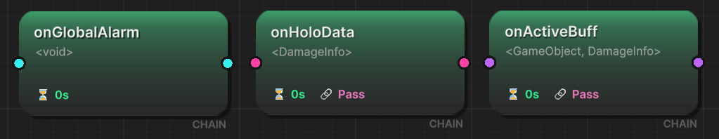
| 🟢 | Chain Node | Sequence (Serial). Fires its task and blocks the flow until completion or duration expires. | Cutscenes, Dialogues, Step-by-step tutorials. |
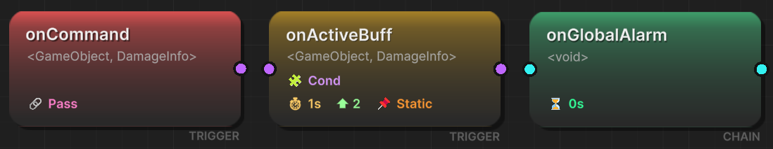
2. Status Badges (The Info Bar)
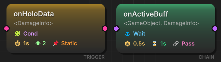
The icons at the bottom of a node give you a complete summary of its internal settings without needing to open the inspector.
| Icon | Label | Logic Type | Meaning |
|---|---|---|---|
| 🧩 | Cond | All | Conditions Active. This node contains a Logic Tree. It will only fire if conditions are met. |
| ⏱ | 0.5s | All | Start Delay. The node waits X seconds before raising the event. |
| ⏳ | 2.0s | Chain 🟢 | Duration. The flow pauses here for X seconds after the event fires (Artificial blocking). |
| ⚓ | Wait | Chain 🟢 | Wait for Completion. The flow pauses until the event's listeners (Coroutines/Async) finish execution. |
| ⬆ | 10 | Trigger 🟠 | Priority. Determines execution order relative to other sibling triggers (Higher = Earlier). |
| 🔗 | Pass | All | Pass Argument. The data from the previous node is passed into this event. |
| 📌 | Static | All | Static Call. Incoming data is ignored. The event fires with default/null arguments. |
3. Data Ports
The Flow Graph enforces Type Safety. The input (left) and output (right) ports are color-coded to base on the Event Argument Type.
Port Legend
| Color | Type | Signature | Description |
|---|---|---|---|
| 🔵 Cyan | Void | () | Simple signal. Carries no data. |
| 🌸 Pink | Single Arg | (T) | Carries one data packet (e.g., float, int, class). |
| 💜 Purple | Double Args | (TSender, TArgs) | Carries the source object and a data packet. |
4. Connection Compatibility
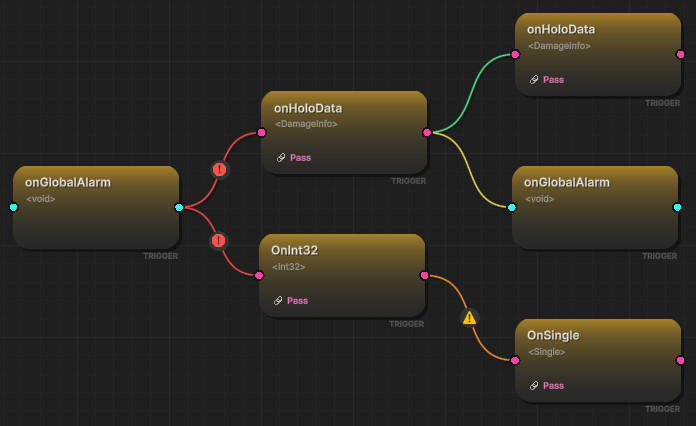
When you drag a line, the color indicates whether the data flow is valid:
| Color | Compatibility | Meaning |
|---|---|---|
| 🟢 Green | Match | Perfect. Types match exactly (e.g., Int → Int). |
| 🟡 Yellow | Compatible | Safe. Incoming data is discarded (e.g., Int → Void). |
| 🟠 Orange | Warning | Auto-Conversion. System generates a runtime converter (e.g., Float → Int). |
| 🔴 Red | Error | Incompatible. Connection is blocked (e.g., String → Int). |
The specific connection color is determined by the combination of the Source Event Type, the Target Event Type, and the Pass Argument configuration on the target node. The table below details the logic for every possible scenario:
| Source Type | Target Type | Pass Argument | Result | Explanation |
|---|---|---|---|---|
| Any | Any | False | 🟢 Green | Config Override: Target ignores input; absolute safety. |
| <Void> | <Void> | True | 🟢 Green | Perfect match. |
| <Void> | <T> | True | 🔴 Red | Target requires T, but Source cannot provide it. |
| <Void> | <S, T> | True | 🔴 Red | Target requires Sender & T, but Source cannot provide them. |
| <T> | <Void> | True | 🟡 Yellow | Safe Discard: Argument T is ignored. |
| <T> | <T> | True | 🟢 Green | Perfect match. |
| <T> | <S, T> | True | 🔴 Red | Target requires Sender, but Source cannot provide it. |
| <S, T> | <Void> | True | 🟡 Yellow | Safe Discard: Sender & T are ignored. |
| <S, T> | <T> | True | 🟡 Yellow | Safe Discard: Sender is ignored. |
| <S, T> | <S, T> | True | 🟢 Green | Perfect match. |
| <T1> | <T2> | True | 🟠 Orange | Risky type conversion (e.g., int -> float). |
| <S, T1> | <T2> | True | 🟠 Orange | Discard Sender + Risky type conversion (Warning priority). |
| <S, T1> | <S, T2> | True | 🟠 Orange | Risky type conversion (e.g., object -> string). |
⚙️ Node Configuration Window
To configure the internal behavior of a node, Double-Click it. This opens the floating configuration window.
1. General Settings
This section applies to all node types.
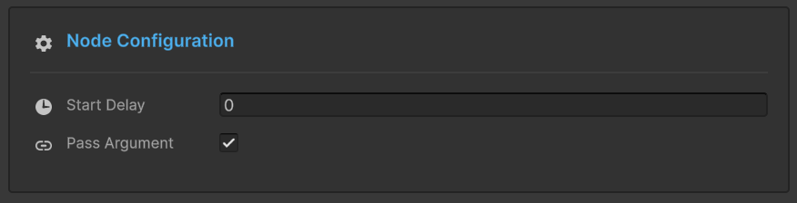
- Start Delay: Time (seconds) to wait before raising the event.
- Pass Argument:
- ✅ Checked: Passes data from the previous node to this one.
- ❌ Unchecked: Fires this event as a standalone "Static" call (Badge: 📌).
2. Logic Specific Settings
The middle section changes based on whether the node is a Trigger or a Chain.
For Trigger Nodes (🟠)
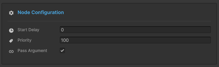
- Priority: An integer value. When a single event triggers multiple downstream nodes, this determines the execution order.
- Example:
Priority 100executes beforePriority 0.
- Example:
For Chain Nodes (🟢)
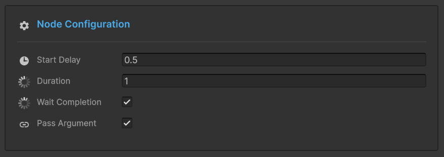
- Node Duration:
- Forces the graph to wait for a specific time after the event fires.
- Use Case: Playing a 3-second animation. Set Duration to
3.0.
- Wait For Completion:
- If checked, the graph intelligently waits for any Coroutines or Async Tasks registered to this event to finish.
3. Node Conditions 🧩
Just like in the Inspector Behavior, you can add a Condition Tree to any node.
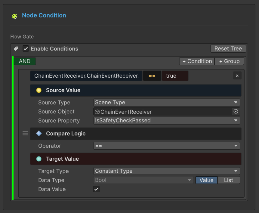
- Logic:
(A AND B) OR C - Behavior: If the condition evaluates to
FALSE, this node will not fire, and the flow stops down this branch. - Use Case: Only play the "Low Health Sound" if
Player.Health < 20.
🖱️ Adding Nodes (The Selector)
When you Right-Click > Add Node or drop a connection into empty space, the Selector Window appears.
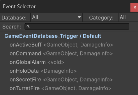
- Search: Fuzzy search your entire database.
- Categorized: Groups events by their folder structure.
- Auto-Wiring: Dropping a connection onto the selector automatically links the new node.
Did you place a Trigger but realized you needed a Chain? Don't delete it! Just Right-Click the Node and select Convert to Chain. All your settings (Delay, Conditions) are preserved.